Faith Can Also Move Composite Gridshells
Written by L. Du Peloux, F. Tayeb, O. Baverel, J-F Caron
1. Introduction
The structure is a gridshell in composite material (Fig. 1a), made up of two kilometers of glass fiber reinforced polymer tubes (GFRP), covered by a PVC coated fabric. An initially flat grid is bent elastically to give the intended shape (Fig. 1b). It is then triangulated with a third layer of pipes so the structure becomes a shell. It weights only 5kg/m2 and covers an area of 350m2 without any internal support. After an architectural and technical presentation of this project, the paper discusses what gridshells are following on from Frei Otto’s work (the association of a structural typology, a flexible material and a specific erection process). It presents recent developments in the area, focusing on the contribution of composite materials. The paper then investigates the overall design process of the structure, from the architect’s sketch to the final gridshell. Each step of this sequential and iterative process is described: 3D modeling, meshing, formfinding, structural analysis and post processing of the geometry. Afterwards, the paper highlights the issue of existing standards, which do not account specifically for composite materials. It explains how this difficulty was overcome. Finally, complexities brought by connections are highlighted. Solutions are identified and validated by tests.
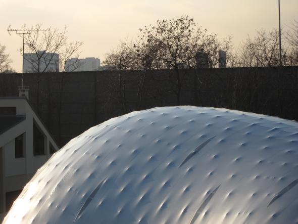
Fig. 1. Exterior view
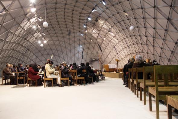
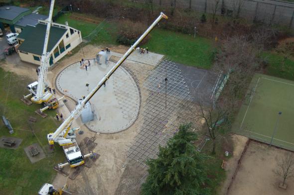
Fig. 1. Interior view (© Camille Moissinac) and grid erection
2. Project Overview
Context and challenges
Creteil is a city of 90.000 inhabitants in the southeast suburb of Paris. It started to urbanize itself in the late 50’s, impelled by the French architect Charles-Gustave Stoskopf. In 1976 he designed Notre Dame of Créteil, a modest catholic church made of concrete, which became a cathedral 10 years later. Recently, the diocese of Créteil has undertaken a major architectural redevelopment project of its cathedral, including a timber shell covering the religious area and the creation of a new cultural area. Once transformed, the edifice shall be more visible, more hospitable and livelier for citizens. Inevitably, such a molt takes time and a temporary place of worship was required to ensure liturgical services during the two-years work. In November 2011, T/E/S/S, the structural design office in charge of the cathedral renovation project, made an ambitious proposal to the diocese. Based on a previous successful experience – the construction of a composite gridshell for the festival Solidays (see video [1]) – T/E/S/S suggested that rather installing a basic tent, the parishioners should construct themselves a temporary cathedral (see video [2]). The overall cost of the project is 400k€, about 30% more than a standard tent of the same size that would have been rented for 2 years.
Architectural form of the building
The generation of the form was driven by two objectives that of providing a variety of appropriate internal spaces within which the community could assemble, and externally to be a welcoming and visually interesting form. Today, the internal organization of a Roman Catholic Church is in large part driven by the post Vatican II vision of a religious celebration being a collective gathering of the community around the Eucharist, center of spiritual life. A circular seating arrangement is often considered the most convivial form to create a sense of belonging while minimizing a sense of hierarchy (Fig. 2).
However the community is not only using the building for religious celebration but also for encounters on a more informal manner, for example spontaneous gatherings after religious ceremonies. In the early Roman church, such gathering of the community was facilitated by the presence of an anti-space to the main space called a narthex, through which one passed on entering the church. It was therefore felt appropriate that the formal freedom which the gridshell system offered would be used to explore forms composed of an agglomeration of major and a minor volumes which contain the two functions: formal and informal gatherings (Fig. 3). Formal explorations were undertaken using modeling clay. The final form is based loosely on two adjacent semi spherical volumes of different size, which are merged into one complex form. Externally the fear of the design team was that the totally convex blob form could look intimidating. It was therefore decided that the two spherical virtual forms, which would be joined to make the final form, would be arranged not in a symmetrical axial manner, but in an asymmetrical curved composition. The resulting form seen in plan is convex on one side and concave on the other. The concave form in plan allows for double curvature to be introduced into what would be otherwise a simpler blob and gives sensuality and visual interest to the building.
Placing of the building on the site
The temporary cathedral is located on a land owned by the municipality, which is used for sporting and other communal gatherings. The curve in the building defines an external area where the church community could meet in the open air and this is where the entrance to the church is situated. The building was positioned on the site so that the entrance addresses a grass planted area forming a garden forecourt or “parvis” (Fig. 3). A service building housing plant, toilets and vestry are housed in a portacabin positioned to the rear of the building.

Fig. 2. In space, a circular form leads naturally to a blob shape.
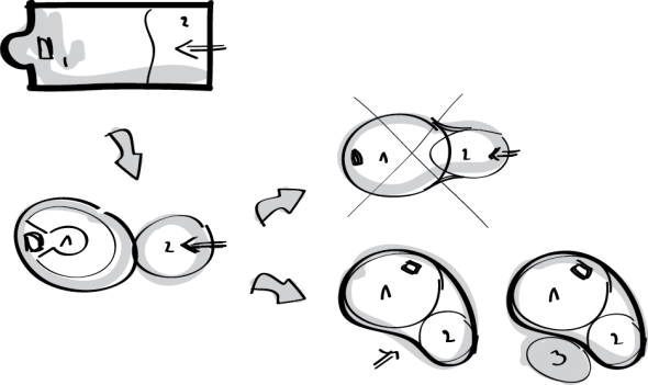
Fig. 3. Major and minor volumes are agglomerated into one volume. (1. celebration area 2. narthex 3. parvis)
Entrance
It is formally quite difficult to integrate doors, which must be verticals, into a complex geometry. Either the gridshell could be deformed to accommodate the geometrical requirements of doors, or the doors could be integrated into an independent form. The latter approach was chosen. In looking for forms to house the doors, reference was made to the conical monumental doorways with rings of concentric decoration, which welcome the faithful to Romanesque and Gothic churches in France. The conical forms were found to by coherent to the overall geometry of the building. The entrance doors were therefore inserted into a conical hooded form made of rolled steel plates and stiffened by concentric steel tubes, which not only make reference to historic precedence but also refer to the gridshell to be discovered inside. The cone of the entrance doors was positioned in the concave side of the building giving access directly to the narthex part of the internal volume (Fig. 4). To the rear of the church is situated a service door. The steel hood, which houses this door, is curved tightly around the door and takes up an ovoid form.
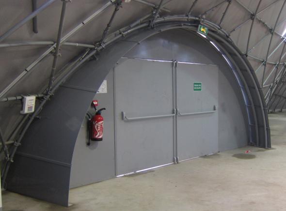
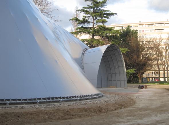
Fig. 4. Main door's exterior and interior views.
Daylight
The gridshell is covered in a PVC membrane, which is opaque. How to introduce daylight into the interior was a major subject of reflection. The simplest way found was to use transparent membrane placed occasionally on the membrane. A small amount of light was required in the interior to create a contemplative atmosphere. The lights would in consequence glow and would be seen as luminous insertions in the vault, like stars in the celestial vault or the apse of some Romanesque churches. The stars were patterned on the joints of the PVC membrane. The almond shape came from simplification of the cutting into the panels either side of the joints and to avoid stress concentrations around cuts in the membrane. This shape, known as Mandela, is frequently used in Marian religious imagery. The distribution of the transparent insertions is quite uniform but gets denser above the pinnacle.
Technical description
The gridshell structure is made of long glass-fiber pipes (∅ext 42mm) pinned together with scaffold swivel couplers. The structural members of the grid, all of different length, are built from one, two or three composite pipes connected with steel sleeves (§6.2). The length of the pipes is restrained to 12m so standard trucks can deliver them. The pipes are organized in three layers. The first two layers are placed perpendicularly on the ground. They form the “quadrangular primary grid”. The distance between the pipes of these two layers is constant so the grid is regular. This primary grid is elastically deformed to obtain the final shape. The third layer of pipes acts as bracing. It gives the structure a shell behavior. Those pipes are fixed to the primary grid once it has been shaped. The structure is anchored to a concrete strip footing with a special steel system, which ensures the transit of loads from the composite structure to the ground. A similar system enables to fix the structure to the doors. A PVC coated fabric, tailor patterned, covers the structure. It includes transparent strips that bring daylight inside. The fabric is stretched on a devoted peripheral edge beam with a double lacing system (halyard and strap). At the ground, the lacing edge beam is made of a bent composite rod nailed regularly to the concrete slab. At the doors, it is made of a steel arch welded to the doorframes. The membrane is waterproof and as a continuous membrane has no joints except at the perimeter. At the perimeter a continuous strip of membrane is prefixed to the internal face of the membrane and fixed to the ground slab being clamped between the concrete and an aluminum flat bar. At the doors, the flexible strip is riveted to the doorframes.

3. Gridshells
Brief history and definition
The inventiveness of the gridshell concept is commonly attributed to Frei Otto, a German architect and engineer who devoted much time to gridshells. In 1975, he achieved the famous Mannheim Multihalle [3] in collaboration with the engineer Edmund Happold (Arup). Thanks to this achievement, the gridshells appeared then among structural typologies allowing various rounded shapes. Literally, the word « gridshell » refers to grids behaving like shells: from a mechanical point of view, stresses acting on the structure are mainly transmitted through compression and traction. Nonetheless, according to the historic evolution of the concept, characterizing a gridshell as the combination of a structural concept – a grid behaving like a shell – and of a specific construction process – using the bending flexibility of the material – seems to be more accurate. The Mannheim project – in which a wooden regular and planar grid, lacking shear stiffness, is elastically deformed up to a selected shape with the help of stays, and then braced and covered – is the launching of this new concept. 25 years later, with the development of the numerical tools, two new projects saw the light: the wooden gridshell of Downland in 2002 [4] and the Savill one in 2006 [5]. The principles of these projects are similar to Mannheim one but new constructive methods are used. In 2000 Shigeru Ban innovates shifting from wood materials to cardboard for the Japan Pavilion at EXPO 2000, in Hannover [6].
Recent developments
Based on this groundwork, the Navier laboratory has developed a research program on gridshells for the last ten years, focused on both the use of new materials and the development of more efficient numerical methods [7]. These developments have been validated by the construction of two prototypes whose areas were about 150 m2 (Fig. 5a and Fig. 5b). project, the forum of the Solidays festival [8]. This achievement, built by voluntary workers, has been the first composite material gridshell to house public (Fig. 5c). Supported by T/E/S/S engineering company and Viry firm, it was an important step for the spreading of the laboratory knowledge. In 2012, the context is favourable for a new achievement named « Temporary Cathedral of Créteil ». Although this gridshell has an area very similar to the Solidays one, the project raised new challenges, in particular the challenge of reliability. Indeed, its period of use is at least two years. Additionally, the skills coming from T/E/S/S company made possible important developments such as for doors, lacing edge beam, anchorages and sleeves. Unlike the two first prototypes, the gridshells built for Solidays and at Créteil are based on a new approach regarding shape-structure relationship. Indeed, thanks to a numerical tool performing the compass method, the geometry of the object is no longer defined as the reversal of a hanging net – in this case, only the flat geometry could be mastered [9] – but now the flat geometry is straight deducted from the one proposed by the architect. This new approach opens up new architectural horizons, making possible the exploration of new shapes and new meshes for gridshells.
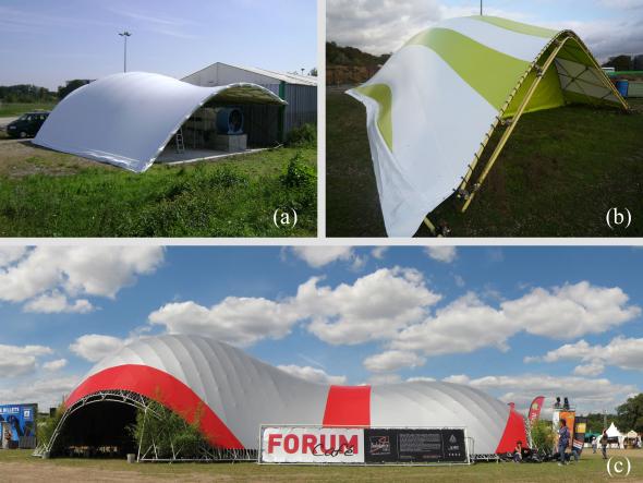
Fig. 5. Prototype (a) & (b) / Solidays 2011 (c)
Gridshell in composite material
The gridshells built in composite material, being at the heart of this paper, are consistent with the framework defined in the section §3.1.
Structural Typology Their mechanical behaviour is very similar to the one of real shells even if the material is discrete and located in a grid more or less open. In spite of that, gridshells benefit from the same advantages as the ones showed by an eggshell: they can cross large span using a low amount of material. Their stiffness is mainly linked to their double-curved shape.
Material Flexibility for Structural Rigidity In this field of application, composite materials like glass fibre reinforced polymer (GFRP) could favourably replace wood, where both resistance and bending ability of the material is sought [10]. The stiffness of the structure does not derive from the intrinsic material rigidity but principally from its geometric curvature. Ideally, the composite profiles are produced by pultrusion, an economic continuous moulded process. The standardization of the process guaranties very stable material and mechanical properties. It frees designers from the painful problematic of wood joining and wood durability. The characterization of this material is presented at §5.3.
Erection Process Usually, the grid morphology is not trivial and leads to design numerous costly and complex joints. To overcome this issue, an original and innovative erection process was developed that takes advantage of the flexibility inherent to slender elements. A regular planar grid made of long continuous linear members is built on the ground (Fig. 6a). The elements are pinned together so the grid has no inplane shear stiffness and can accommodate large-scale deformations during erection (Fig. 6b). Then, the grid is bent elastically to its final shape (Fig. 6c). Finally, the grid is frozen in the desired shape with a third layer of bracing members (Fig. 6d) and the structure becomes a shell.
Nota: Other ways to triangulate the grid could be investigated, like cables. Moreover, it could be interesting to freeze the grid in a nonrelaxed position, so the exact intended form is achieved.

Fig. 6. Assembly (1) / Erection (2) / Erected grid (3) / Braced grid (4)
4. From shape to shell
Overall design process
The goal of the design process is to identify a gridshell structure that works and which respect as faithfully as possible the architectural project – a shape and a program. It represents “the path from shape to structure”. Its progress, sequential and iterative, revolves around three major stages: shape, mesh and structure (Fig. 7). It is not trivial to go through this complex process. Indeed, for each step, the method, the tool, the criteria, that offer both a sufficient explorative richness to find out enough candidate solution, and the means to evaluate and compare the suitability of those solution, have to be found. In the next part of this paper the authors present, for each previously mentioned stage, the studied options and the selected evaluation criteria.
From sketch to shape
The first step of the process consists in building a precise geometric model from the sketch of the architect and to evaluate its mechanical potential (Fig. 8). At this stage, the goal is to estimate the probability a given shape would lead to the generation of a structurally feasible gridshell. Stresses in the grid are mainly due to the bending of the profiles. They derive directly from their geometric curvature. Thus, the principal curvatures of the surface – because they give a qualitative measurement of the local curvature of any curve drawn on a surface – are relevant indicators to evaluate the stress rate of a grid laying on it. Particularly, one should ensure the following condition is satisfied everywhere, where r is the pipe’s outer radius, Rmin is the minimum principal radius, E is the flexural modulus, σk,flex the characteristic flexural strength (§5.3) and γlt the long-term partial coefficient of material resistance (§5.4) :
(1)
Ideally, the shape is controlled by few key parameters. Thus, it can be adapted and optimized through an iterative process, towards this criterion (1).
From shape to mesh
During the second step, the candidate surface is meshed and the mechanical potential of the resulting grid is evaluated. At this stage, we try to estimate the probability a given mesh could lead to the generation of a viable gridshell structure (Fig. 9). Simultaneously, meshes are compared according to their architectural relevance. This time, the geometric curvature of the polylines drawn on the surface is the criterion to characterize the mechanical potential of the grid. In particular, one should ensure the following condition is satisfied everywhere, where Rspline is the spline’s local curvature radius:
(2)
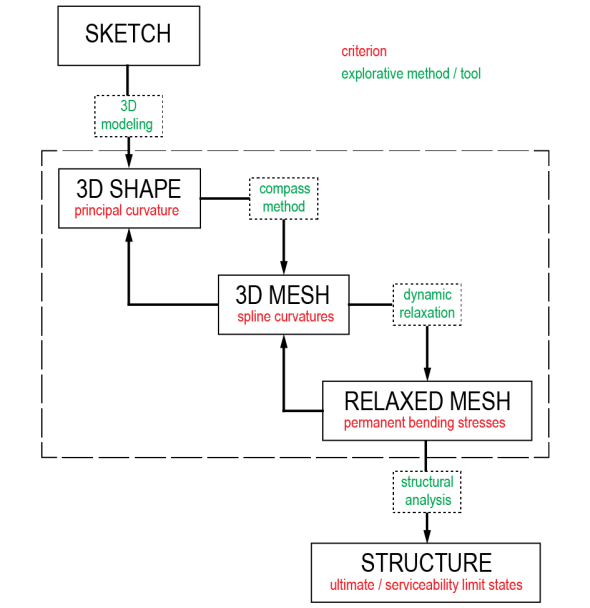
Fig. 7. Design process from shape to shell.
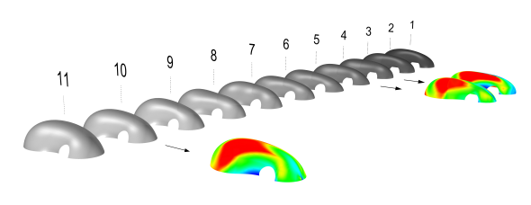
Fig.8. Selection of 3 slightly different 3D shapes, derived from the targeted shape, based on an analysis of their principal curvatures.
The mesh is obtained by the compass method, described in [11], which develops a regularly spaced grid on a surface from two secant directrix. For a given shape there are an infinite number of meshes. The aim is to identify at least one grid, suitable towards architectural and structural criteria (Fig.9). The laboratory tried various numerical methods to generate such grids [12]. Here, a specific software [13], developed for rhino & grasshopper, allows generating this kind of mesh on any nurbs surface. It performs the following elementary operations: surface meshing with the compass method, trimming, control of geometry’s integrity and flattening of the grid. The tool also generates automatically a text file, which can be imported in structural analysis software, containing all the required information to perform the formfinding of the structure. An add-on facilitates loads application of various complexities (snow, wind, etc.), which is tricky for free forms.
Formfinding: from mesh to structure
From now on, the initial form has been optimized and promising meshes for the materialization of the future gridshell have been identified. However, they do not take account of any true mechanical reality, because only geometric rules have led to their generation. The formfinding step consists precisely in finding the mechanical equilibrium geometry of a grid, and the corresponding permanent bending stresses.The calculations, performed numerically thanks to a dynamic relaxation algorithm with kinetic damping [14], is composed of the steps in the following table (Table 2).
Two analysis models are built during this process to study the structure with or without bracing pipes. Note that the algorithm has been improved to take account for the eccentricity due to connections [15].
Structural analysis
A full structural analysis is performed on the gridshell, using the two mechanical models created previously during the formfinding stage. The non-braced model is used to check the grid’s behavior during the construction stages. In particular, it must be verified that the primary grid - the one with no triangulation pipes - has no risk of buckling, both for obvious safety reasons and to ensure the accuracy of the final geometry. Indeed, the more the form is likely to buckle, the more it can be triangulated in a buckled geometry different to the targeted geometry. The model with the triangulated grid is used to confirm the gridshell complies with all the structural requirements during its lifetime. Its behavior under standard loadings is evaluated.
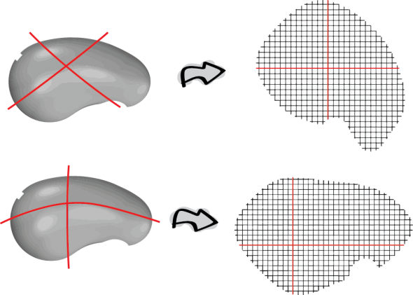
Fig. 9. Resulting meshes and flat grids, depending the directrix.

From the analysis model to the as-built geometry
Previously, the geometric and structural models employed during this project never took account for the eccentricity between the three layers of pipes, inserted by the connectors. Although the mechanical consequences of this eccentricity could be neglected to a first-order approximation, this is not the case for the geometric consequences it induces. Indeed, the eccentricity remains small compared to the span of the shell but is not negligible compared to the mesh size (e = 8cm / l = 17m / w = 1.00m). Thus, pipes length and anchorages position could not be determined with sufficient accuracy without giving back to the gridshell its “thickness”. The employed method, purely geometric, assesses the neutral fibre of the shell is equidistant from the first two layers of pipes. Remind that the formfinding is performed only with those two layers. Connexion’s axes are supposed to be parallel to the local normal of the shell’s surface. This assumption is not exact but, in this case, it gives a sufficient accuracy. The red pipe is offset -e/2, the green +e/2 and the blue +3e/2 along the normal (Fig. 11).
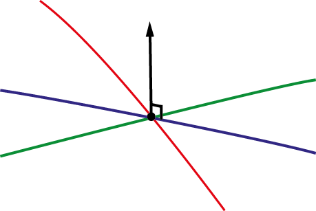
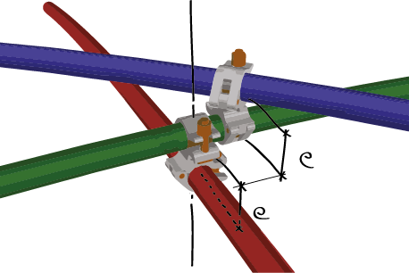
Fig. 11. Restoring the geometric eccentricity between layers.
5. Standards: issues with composite materials
Beyond the technical difficulties related to both design and structural analysis of the shell, the regulatory framework was a vital issue for the project’s success. Because it was the first time a structure of this kind would host regularly a large number of people in a long-term period, the question of its reliability over time was a major issue. To be built the gridshell had to comply with existing standards, which do not take into account such an innovative edifice, all in composite material. The strategy adopted to bypass this obstacle is presented later in the publication.
First level: administrative classification of the building
The first level, administrative, consisted in getting from the French authorities an appropriate classification for the building, regarding the project’s reality: a lightweight structure with a short lifespan. As expected, the edifice was classified as a “building open to the public” form the category “big tops & tents” [16]. In this classification, construction procedures and regulations are adapted to the short lifespan of buildings.
Second level: compliance with existing standards
The second level, normative, consisted in making the most of the existing regulatory framework to justify the compliance of a structure that would not, at first sight, be taken into account by standards that does not include composite materials. As far as possible, the design was led in compliance with the Eurocodes, where the structural design is made according to limit states under normalized loadings (self-weight, snow, wind, etc.). Despite the Eurocodes do not directly take into account composite materials, they propose some probabilistic methods to introduce new materials (Annexe D). As far as possible, the mechanical properties of the GFRP pipe were determined by tests in conformance with these methods. Otherwise, values where taken according to the Eurocomp [17]. In some cases, as the sleeve, the design of the construction details has also benefited from this approach.
Nota: The Eurocomp is a kind of pre-standard intended for the structural design of buildings and civil engineering works in GFRP composites, consistent with the Eurocode approach. It is considered has the referent design code in the matter.
Characteristic flexural strength of the pipes
Naturally, the characteristic flexural strength (σk,flex) of the GFRP pipe is needed to verify if the structure complies with Eurocodes. This parameter has a critical impact on the structure’s reliability because in this particular application stresses in pipes are mainly due to bending. Thus, it was important to confirm the manufacturer’s value by assays. Three-point flexural tests were led with and without connexions (tightening torque set to 20Nm) to determine the characteristic strength according to the protocol of the Eurocode (Annex D):
(3)
For five tests, the factor kn,5% is 1.80 , assuming a normal distribution. One can note that the connections scatter the results more. Finally, the manufacturer value of 400MPa (ASTM D790) was confirmed and retained for further calculations.
6. CONSTRUCTION DETAILS
Mies Von der Rohe liked to say: “God is in the details”, thus expressing that the quality of a building highly relies on the care taken in designing project’s details. In this part, after a brief review of the project construction details, the authors focus on the design of a sleeve for connecting composite pipes.
Overview on construction details
In this project, one can identify 4 major structural details: the swivel coupler for connecting composite pipes to assemble the grid (Fig. 12a); the steel sleeve for connecting several composite pipes to make long members from initially short piece of tubes (Fig. 12b); ground anchorages for fixing the structure to the concrete slab (Fig. 12c) and the lacing edge beam of the fabric (Fig. 12d). Note that the tricky issue of connecting steel and composite parts is solved in a similar way through sleeve and anchorage details.

Fig. 12 Major construction details.
Sleeve
Sleeves are major components in the structural system. The presented component is a great innovation compared to the composite gridshells built previously, where members were simply interrupted or overlapped. By establishing mechanical and architectural continuities between pipes, this sleeve brings closer the real behavior and the theoretical behavior of the shell.
7. Conclusions
This paper has presented the different steps for the design of a gridshell in composite material: a Temporary Cathedral at Créteil, in Paris suburb, in 2013. The first step was the optimization of the shape in order to avoid concentrations of curvature, locally. The second step showed a tool to automatically mesh a surface using the compass method. With this tool, the orientation of the mesh is studied according to structural and architectural criterions. The last steps showed the structural analysis of the gridshell and how to get the as-built geometry from the analysis model. Architecturally, the structure offers a very interesting space where the textual richness of the pipes against the membrane accentuates the reading of the complex curved surfaces. This project demonstrates that gridshells in composite material are suitable for constructing freeform buildings. However, the long-term behavior of these materials needs to be better characterized to extend their lifespan. This is one of the laboratory’s research projects. At the moment, further developments are also conducted by the laboratory to take account for torsional effects and non axisymmetric sections in such structures, as it is studied in [20]. The interaction between the structure and the fabric is also a vast research field to be explored.
8. Références
[1] Video of the Forum Solidays project (2012), http://www.youtube.com/watch?v=24LLfcVIZWw
[2] Video of the Temporary Cathedral of Créteil project (2013), http://vimeo.com/59726330
[3] Happold E., Lidell W.I., Timber lattice roof for the Mannheim Bundesgarten-schau, The Structural Engineer, Vol. 53, No. 3 (1975) pp. 99-135.
[4] Harris R., Rohmer J., Kelly O., Johnson S., Design and construction of the Downland Gridshell, Building Research & Information, Vol. 31, No. 6 (2003) pp. 427-454.
[5] Harris R., Haskins S., Roynon J., The Savill Garden gridshell: design and construction, The Structural Engineer, Vol. 87, No. 17 (2008) pp. 27-34.
[6] Ban S., The Japanese pavilion, In: McQuaid M. (ed) Shigeru Ban, Phaedon (2006) pp. 8-11.
[7] Douthe C., Study of slender prestressed structures in composite materials: application to the conception of gridshells, PhD thesis, ENPC (2007) pp. 274.
[8] Baverel O., Caron JF., Tayeb F., du Peloux L., Gridshells in Composite Materials: Construction of a 300m2 Forum for the Solidays' Festival in Paris, Structural Engineering International (IABSE), Vol. 22, No. 3 (2012) pp. 408-414.
[9] Addis B., “Toys that save millions” - a history of using physical models in structural design, The Structural Engineer, Vol. 91, No. 4 (2013) pp. 12-27.
[10] Douthe C., Baverel O., Caron JF., Gridshell structures in glass fibre reinforced polymers, Construction and Building Materials, Vol. 24, No. 9 (2010) pp. 1580-1589.
[11] Otto F., Hennicke J., Matsushita K., Gitterschalen Gridshells, Institut für Leichte Flächentragwerke (1974).
[12] Bouhaya L., Baverel O., Caron JF., Mapping two-way continuous elastic grid on an imposed surface: Application to grid shells, Proceedings of the IASS Symposium, Valencia (2009).
[13] du Peloux L., Baverel O., Caron JF., Tayeb F., From shape to shell: a design tool to materialize freeform shapes using gridshell structures, Proceedings of the Design Modeling Symposium, Berlin (2013).
[14] Barnes M., Applications of dynamic relaxation to the topological design and analysis of cable, membrane and pneumatic structures, 2nd Int. Conference on Space Structures, (1975) pp. 211-219.
[15] Douthe C., Baverel O. and Caron JF., Form-finding of a grid shell in composite materials, Journal of the IASS, Vol. 47, No. 150 (2006) pp. 53-62.
[16] Règlement ERP type CTS (big tops & tents), http://www.sitesecurite.com/portail/AD_ERP/ERP_05.asp
[17] Clarke J.L., Structural Design of Polymer Composites - Eurocomp, E & FN Spon (1996)
[18] Kotelnikova N., Mechanical and thermal optimization of fiberreinforced plastic building envelope, PhD thesis, ENPC (2012).
[19] Bank LC., Composites for Construction: Structural Design with FRP Materials, Wiley J. & Sons (2006).
[20] Barnes M., Adriaenssens S., Krupka M., A novel torsion/bending element for dynamic relaxation modeling, Computers & Structures, Vol. 119, No. 1 (2013) pp 60–67